General Purpose I/O(e)
In this chapter, I will discuss the GPIO pins that the Raspberry Pi can use for communication with the outside world. Ideally, a pin is connected to an LED on the board so that we can initially forego external hardware and effectively see a result. Among bare-metal programmers, this is closest to a "Hello World" program. In the first subchapter, we will make the LED blink. In the next one, we will try to bring some structure to the source code and then improve the code so that the functions can be used more universally.
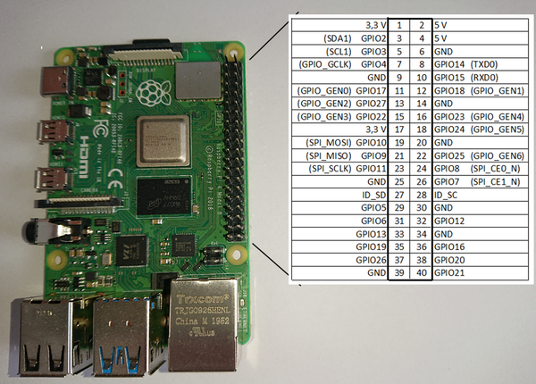
The Raspberry Pi has several GPIO pins that are particularly interesting for hardware enthusiasts as they are easy to program and can connect well with the outside world. The Raspberry Pi 4 has 40 GPIO pins, of which 26 can be programmed as either input or output. Here is a summary of the 40 pins and their assignments:
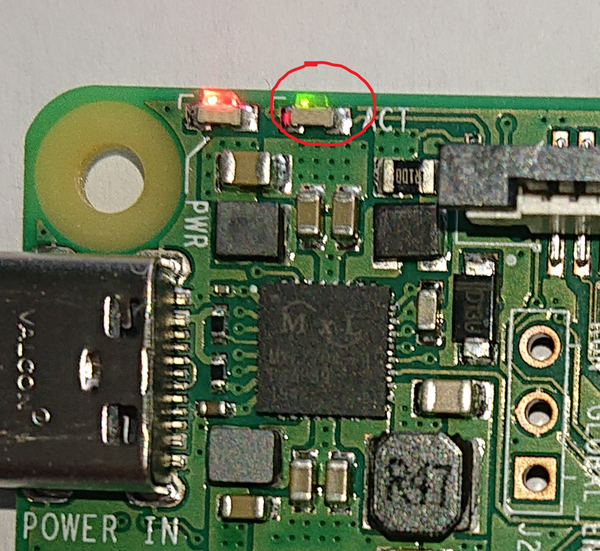
Additionally, there are other internal GPIO addresses that can be programmed through the programming interface. One of these is the green LED, which can be controlled through Port 42 on the Raspberry Pi 4.
Making the LED Light Up
As already mentioned, there is a green LED on the Raspberry Pi 4 that we can control via software to turn on and off. This is controlled via Port 42. On older models, the address is different. Check the appendix for these addresses. In the chapter “Advanced Functions for the LED”, it is very easy to control the LED accordingly, but do not forget to change the base address of the Raspberry in the “base.inc” file.
First, the complete source code:
.equ RPI_BASE, 0xFE000000
.equ GPIO_BASE, RPI_BASE + 0x200000

@ GPIO function select (GFSEL) registers have 3 bits per GPIO
.equ GPFSEL0, GPIO_BASE + 0x0   @GPIO select 0
.equ GPFSEL1, GPIO_BASE + 0x4   @GPIO select 1
.equ GPFSEL2, GPIO_BASE + 0x8   @GPIO select 2
.equ GPFSEL3, GPIO_BASE + 0xC   @GPIO select 3
.equ GPFSEL4, GPIO_BASE + 0x10  @GPIO select 4

@GPIO SET/CLEAR registers have 1 bit per GPIO
.equ GPSET0, GPIO_BASE + 0x1C @set0 (GPIO 0 - 31)
.equ GPSET1, GPIO_BASE + 0x20 @set1 (GPIO 32 - 63)
.equ GPCLR0, GPIO_BASE + 0x28 @clear0 (GPIO 0 - 31)
.equ GPCLR1, GPIO_BASE + 0x2C @clear1 (GPIO 32 - 63)
This part of the source code will be inserted into our initial file between lines 4 and 5. This part generates variables that are available to the assembler during compilation.
/*
* LED is Pin42
* on the GPFSEL4 register Bits 8-6
* 001 = GPIO Pin 42 is an output
*/

   mov r1, #1
   lsl r1, #6  /* -> 001 000 000 */

/*
* 0x10 GPFSEL4 GPIO Function Select 4
*/

   ldr r0, =GPFSEL4
   str r1, [r0]

/*
* Set the 42 Bit
* 25:0 SETn (n=32..57) 0 = No effect; 1 = Set GPIO pin n.
* 42 - 32 = 10
*/

   mov r1, #1
   lsl r1, #10

MainLoop:  @Infinite loop

/*
* 0x2C GPCLR1 GPIO Pin Output Clear 1
*/

   ldr r0, =GPCLR1 @LED is off
   str r1, [r0]

/*
* Waiting
*/

   mov r2, #0x3F0000
wait1$:
   sub r2, #1
   cmp r2, #0
   bne wait1$

/*
* 0x20 GPSET1 GPIO Pin Output Set 1
*/

   ldr r0, =GPSET1 @LED is on
   str r1, [r0]

/*
* Waiting
*/

   mov r2, #0x3F0000
wait2$:
   sub r2, #1
   cmp r2, #0
   bne wait2$

   b MainLoop
And the actual program.
If you don’t feel like typing all of this, you can also download the source as zweites.s.
So now you see what happens. Compile it following the above-mentioned scheme. Replace “erstes” with “zweites” and follow the instructions as described above. The specified LED will start blinking after a boot.
First, I describe the new commands I have used here, and then I describe how the program works.

