General Purpose I/O(e)
In this chapter, I will discuss the GPIO pins that the Raspberry Pi can use for communication with the outside world. Ideally, a pin is connected to an LED on the board so that we can initially forego external hardware and effectively see a result. Among bare-metal programmers, this is closest to a "Hello World" program. In the first subchapter, we will make the LED blink. In the next one, we will try to bring some structure to the source code and then improve the code so that the functions can be used more universally.
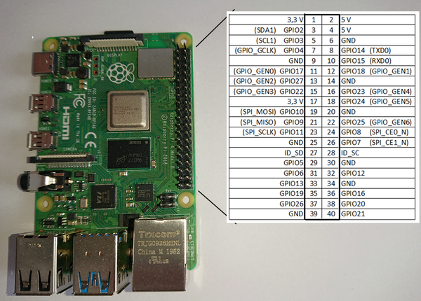
The Raspberry Pi has several GPIO pins that are particularly interesting for hardware enthusiasts as they are easy to program and can connect well with the outside world. The Raspberry Pi 4 has 40 GPIO pins, of which 26 can be programmed as either input or output. Here is a summary of the 40 pins and their assignments:
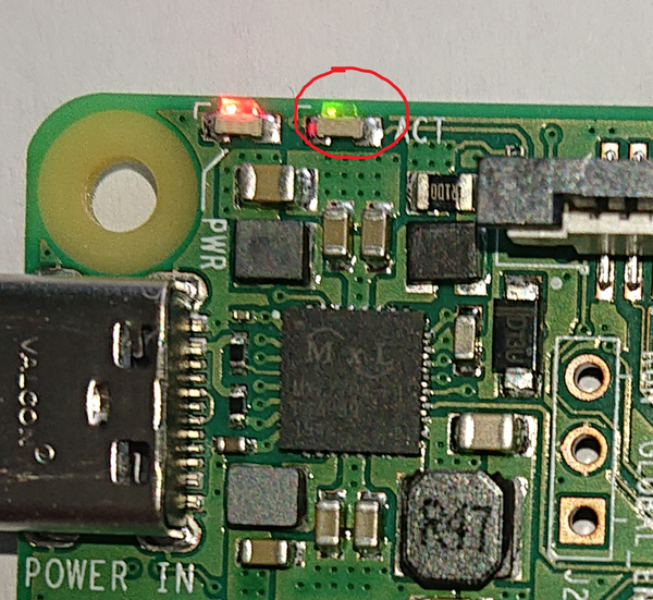
Additionally, there are other internal GPIO addresses that can be programmed through the programming interface. One of these is the green LED, which can be controlled through Port 42 on the Raspberry Pi 4.
Making the LED Light Up
As already mentioned, there is a green LED on the Raspberry Pi 4 that we can control via software to turn on and off. This is controlled via Port 42. On older models, the address is different. Check the appendix for these addresses. In the chapter “Advanced Functions for the LED”, it is very easy to control the LED accordingly, but do not forget to change the base address of the Raspberry in the “base.inc” file.
First, the complete source code:
.equ RPI_BASE, 0xFE000000
.equ GPIO_BASE, RPI_BASE + 0x200000

@ GPIO function select (GFSEL) registers have 3 bits per GPIO
.equ GPFSEL0, GPIO_BASE + 0x0   @GPIO select 0
.equ GPFSEL1, GPIO_BASE + 0x4   @GPIO select 1
.equ GPFSEL2, GPIO_BASE + 0x8   @GPIO select 2
.equ GPFSEL3, GPIO_BASE + 0xC   @GPIO select 3
.equ GPFSEL4, GPIO_BASE + 0x10  @GPIO select 4

@GPIO SET/CLEAR registers have 1 bit per GPIO
.equ GPSET0, GPIO_BASE + 0x1C @set0 (GPIO 0 - 31)
.equ GPSET1, GPIO_BASE + 0x20 @set1 (GPIO 32 - 63)
.equ GPCLR0, GPIO_BASE + 0x28 @clear0 (GPIO 0 - 31)
.equ GPCLR1, GPIO_BASE + 0x2C @clear1 (GPIO 32 - 63)
This part of the source code will be inserted into our initial file between lines 4 and 5. This part generates variables that are available to the assembler during compilation.
/*
* LED is Pin42
* on the GPFSEL4 register Bits 8-6
* 001 = GPIO Pin 42 is an output
*/

   mov r1, #1
   lsl r1, #6  /* -> 001 000 000 */

/*
* 0x10 GPFSEL4 GPIO Function Select 4
*/

   ldr r0, =GPFSEL4
   str r1, [r0]

/*
* Set the 42 Bit
* 25:0 SETn (n=32..57) 0 = No effect; 1 = Set GPIO pin n.
* 42 - 32 = 10
*/

   mov r1, #1
   lsl r1, #10

MainLoop:  @Infinite loop

/*
* 0x2C GPCLR1 GPIO Pin Output Clear 1
*/

   ldr r0, =GPCLR1 @LED is off
   str r1, [r0]

/*
* Waiting
*/

   mov r2, #0x3F0000
wait1$:
   sub r2, #1
   cmp r2, #0
   bne wait1$

/*
* 0x20 GPSET1 GPIO Pin Output Set 1
*/

   ldr r0, =GPSET1 @LED is on
   str r1, [r0]

/*
* Waiting
*/

   mov r2, #0x3F0000
wait2$:
   sub r2, #1
   cmp r2, #0
   bne wait2$

   b MainLoop
And the actual program.
If you don’t feel like typing all of this, you can also download the source as zweites.s.
So now you see what happens. Compile it following the above-mentioned scheme. Replace “erstes” with “zweites” and follow the instructions as described above. The specified LED will start blinking after a boot.
First, I describe the new commands I have used here, and then I describe how the program works.
New Commands
.equ
.equ itself is not an assembler instruction for the processor. It gives an instruction to the assembler itself. .equ tells the assembler to create a variable with a specific value. This allows the programmer to use a variable name instead of specific numerical values. Alternatively, the .set command can also be used, which has the same function. For example:
.equ RPI_BASE, 0xFE000000
Here, the variable "RPI_BASE" is assigned the value "0xFE000000". Additionally, calculations can also be performed here.
.equ GPIO_BASE, RPI_BASE + 0x200000
This means that the value of "RPI_BASE" is added to the value "0x200000", resulting in "0xFE200000".
But what do these values mean?
The Raspberry Pi uses address registers that take over certain functions. These are offered at a specific address in the Raspberry Pi's memory, which we are allowed to use. These registers are described in the document BCM2711 ARM Peripherals and how they are to be used. The first value (RPI_BASE) we set is the fundamental address of the peripherals as visible to the ARM (Page 10). For the Raspberry Pi 4, this address is 0xFE000000. It is different for older models. In the appendix “Base addresses of the models”, I have listed these. If another model is being used, this base address must be adjusted accordingly here. To control the LED, we use the GPIO register. According to the documentation (Page 83), this would be "0x215000". Through testing, however, I can say that this cannot be correct. In previous models, the address was "0x200000" and this also works on the Raspberry Pi 4. Unfortunately, there are some errors in the documents, and in case of doubt, the Raspberry Pi community is helpful. The remaining values are taken from Chapter 5.2 of the document and defined as variables.
Registers
Let's get to some fundamentals. In a processor, there are registers that allow the processor to compute quickly. On the ARM, there are 16 of these, R0-R15 and CPSR. The registers R13-R15 also have other functions. R13 is also called the stack pointer (SP), R14 the link register (LR), and R15 the program counter (PC). Generally, these three registers should only be used for these purposes. CPSR is the status register, which can also be called APSR. This contains a copy of the status flags of the Arithmetic Logic Unit (ALU). They are also called condition code flags. The processor uses them to determine whether conditional instructions should be executed or not.
| R0 | R1 | R2 | R3 | R4 | R5 | R6 | R7 | R8 | R9 | R10 | R11 | R12 | R13 (SP) |
R14 (LR) |
R15 (PC) |
CPSR |
ldr (Load Register)
The ldr command loads a 32-bit number from memory and writes it into a register.
ldr r0, =GPFSEL4
In our case, we assign r0 the number from GPFSEL4 (0xFE200010). However, the ARM cannot do this directly as written. Here we use a function of the assembler that stores this number in memory and the assembler enters this address there. Essentially, we could do the same by creating this address ourselves and referencing it. This will come up in a later part of the course.
lsl (Logical Shift Left)
With lsl, you can shift bits to the left. In this case, the bits are shifted to the left.
As an example from our code:
lsl r1, #6
Here, the content of r1 is shifted 6 places to the left.
For example, if we assign r1 with 0x1, this number looks as follows in binary code:
0000 0000 0000 0000 0000 0000 0000 0001
If we now shift it 6 places to the left as described above, the binary code becomes:
0000 0000 0000 0000 0000 0000 0010 0000
sub (Subtract)
As the command suggests, something is subtracted here.
sub r2, #1
In our example, the content of register r2 is subtracted by 1.
cmp (Compare)
The cmp command compares data and fills the CPSR register with the result. We already use it in the next command.
cmp r2, #0
Here in the example, r2 is compared with "0".
bne (Branch if Not Equal)
We have already mentioned the b command in the previous part of the course. b means that we should jump to another address. Here, an ARM peculiarity is used. The ARM can execute most of its commands with conditions controlled by the status register. There are some conditions that will be described in the next section.
bne wait1$
In our example, the jump is only executed if the result of the previous command was not equal. If the result was equal, the command is ignored, and the next instruction is executed.
Condition Code
Most ARM commands can be given a condition code. The following suffixes are possible, which are simply appended to the corresponding command:
| SUFFIX | MEANING |
|---|---|
| EQ | Equal |
| NE | Not Equal |
| CS or HS | Higher or Same (unsigned) |
| CC or LO | Lower (unsigned) |
| MI | Negative |
| PL | Positive or Zero |
| VS | Overflow |
| VC | No Overflow |
| HI | Higher (unsigned) |
| LS | Kleiner oder gleich (ohne Vorzeichen) |
| GE | Größer oder gleich (ohne Vorzeichen) |
| LT | Less Than (signed) |
| GT | Greater Than (signed) |
| LE | Less Than or Equal (signed) |
| AL | Always (usually not written) |

